Steam turbine casings are critical components in power generation, but they face significant challenges over years of operation. Repeated exposure to high thermally induced stress often exceeds the yield point of the material, leading to various issues that can compromise performance and reliability.
As steam turbine casings operate under extreme conditions, stresses can become locked within the material. This phenomenon causes the casings to distort, creating gaps at the split line when the assembly is loosened. To achieve a metal-to-metal seal fit, technicians often find themselves over-torqueing the bolts, which can exacerbate the problem and lead to further complications.
The conventional approach to ensuring a proper seal involves a series of labour-intensive steps:
- Cover Installation:
The turbine cover is placed onto the casing. - Bolts Torquing:
Bolts are torqued to close the gap until it disappears. - Cover Removal:
The cover is taken off to inspect the seal. - Seal Imprint Measurement:
Technicians measure the seal imprint to assess contact quality. - Surface Preparation:
Any excess material on the seal surface is meticulously scraped off. - Repetition:
The entire process is repeated until a 0.0015-inch (0.038mm) feeler gauge cannot be inserted anywhere along the horizontal joint.
This tedious process not only consumes valuable time but can also lead to inconsistencies and inaccuracies in the final seal. The traditional method of achieving a proper seal in steam turbine casings comes with several drawbacks:
- Increased Downtime:
The repetitive nature of the process leads to significant downtime during maintenance, which can affect overall plant efficiency. - Inconsistent Results:
Human error in measurement and handling can result in variable seal quality. - Risk of Damage:
Over-torquing bolts to close gaps risks damaging the casing, compromising its structural integrity.


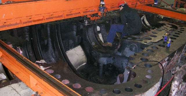
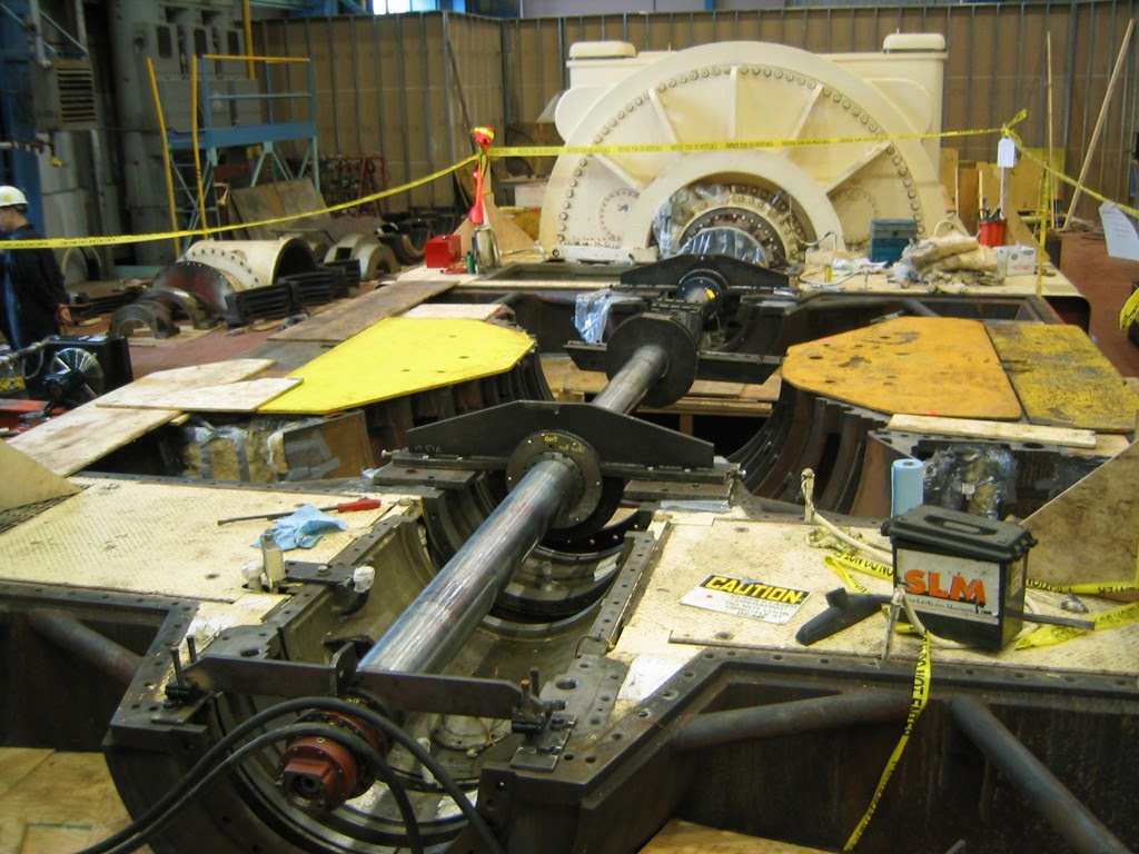
Machining scope of High and Low Pressure Casing
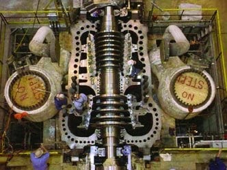
Modern turbines, particularly those operating under steam pressures exceeding 100 bar and with power ratings greater than 100 MW, often utilize a double-shell design. This innovative configuration features a space between the casings that is filled with steam at exhaust conditions. This design allows for smaller temperature and pressure differentials, enhancing efficiency and durability.
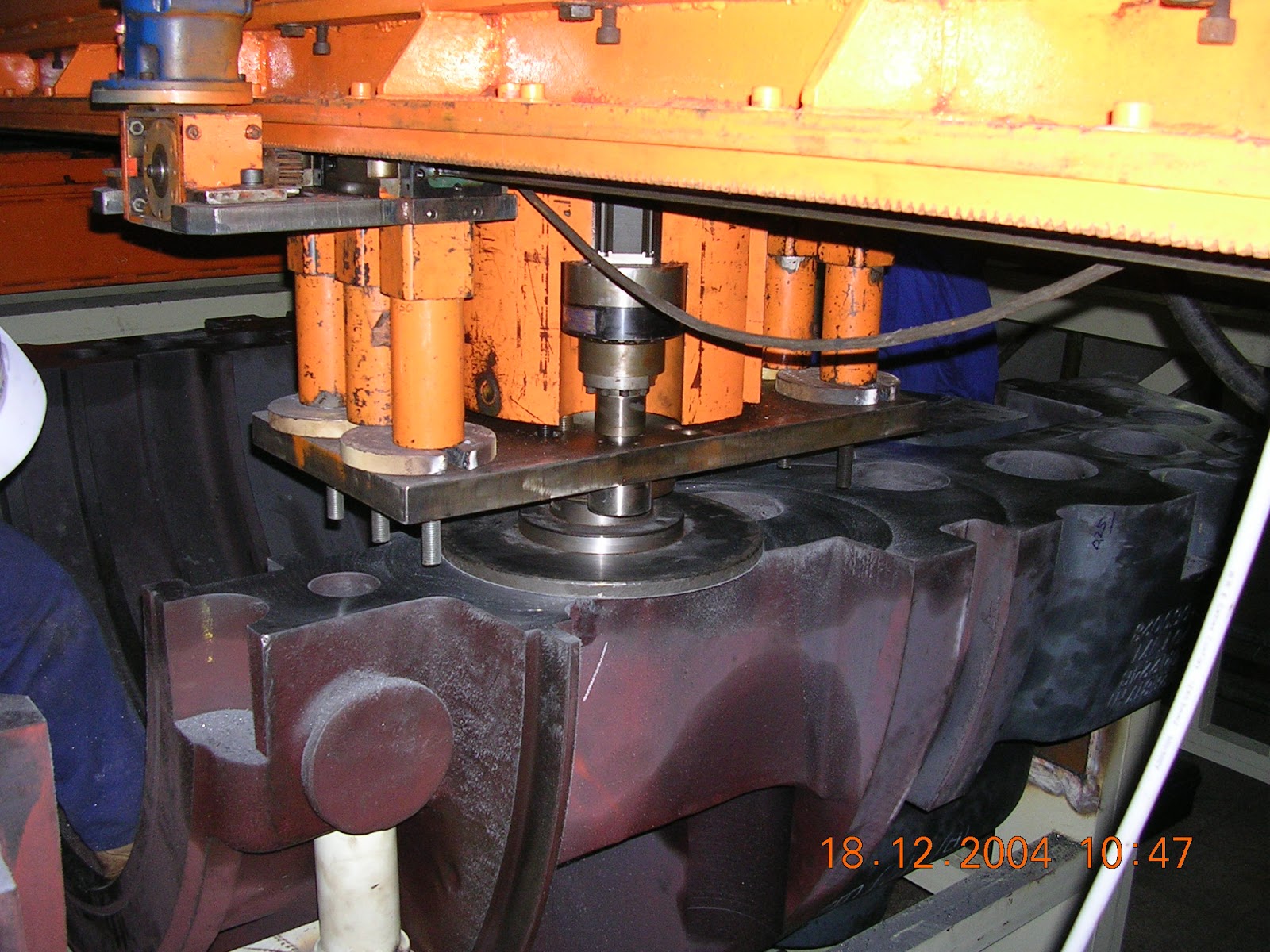
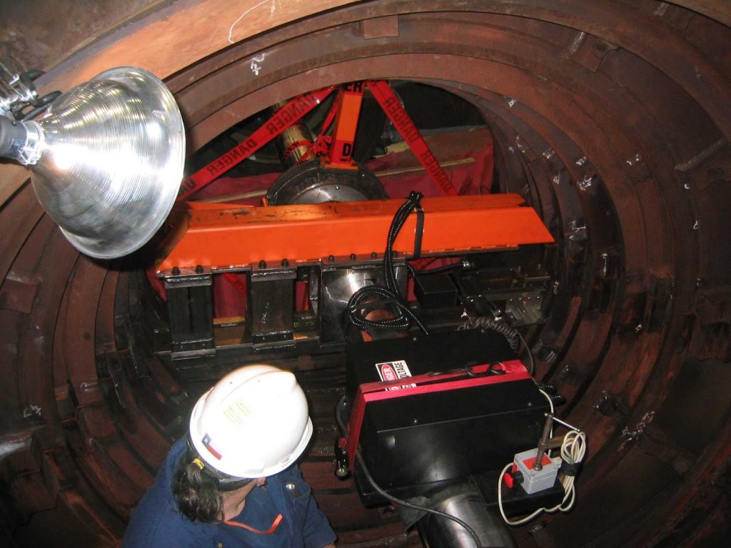
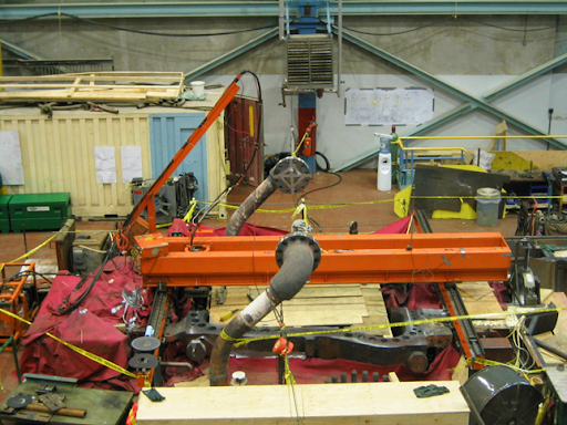
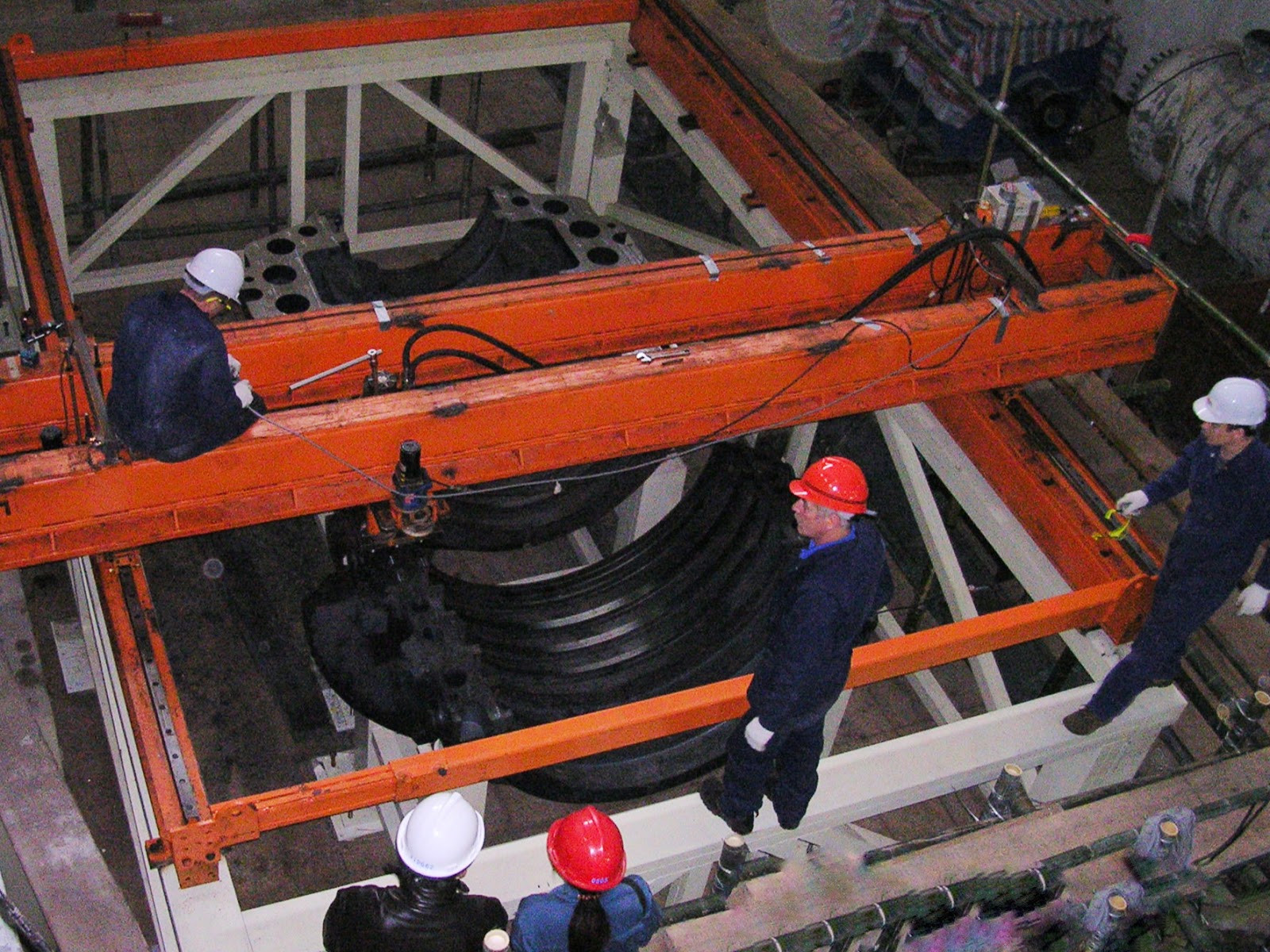
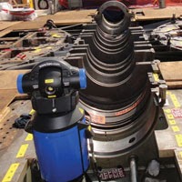
To ensure a proper metal-to-metal seal fit for both the inner and outer casings, in-situ laser-controlled milling techniques can be employed. This advanced method achieves a surface runout of just 0.05mm, ensuring a precise fit. Customized jigs are designed and fabricated to securely hold the linear milling machine in place, allowing for effective machining of the top inner and outer casings.

(1)

Importance of Horizontal Split Line Machining
When machining the horizontal split line, it is crucial to consider that this process lowers the turbine centerline. Consequently, diaphragm fits must be bored to provide adequate radial clearance for proper diaphragm positioning at operating temperatures. This task can be efficiently executed using an in-situ boring machine, ensuring precision and reducing downtime.
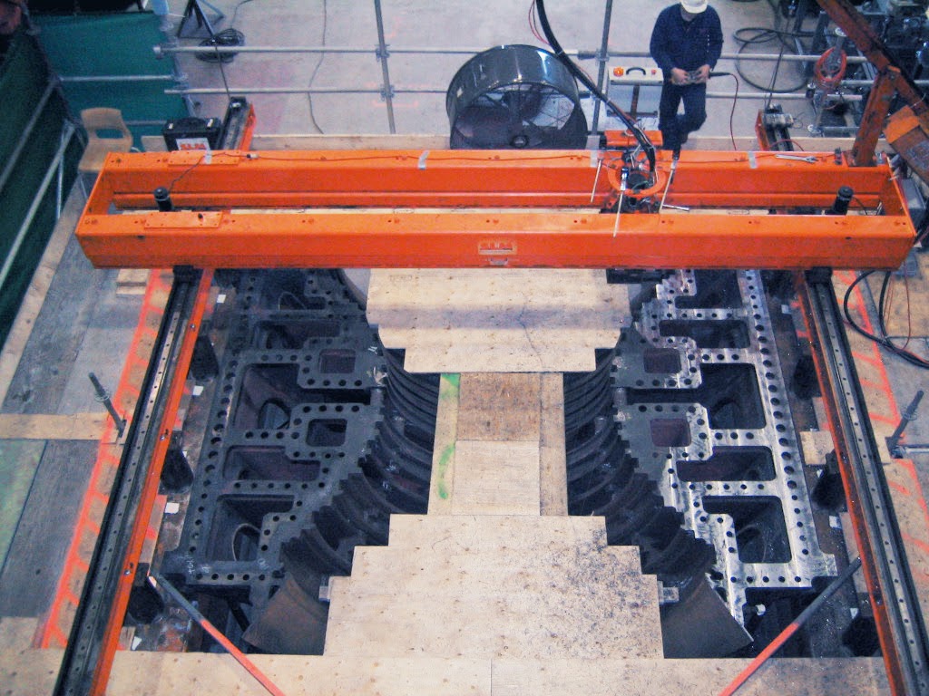
To achieve metal to metal seal fit for both inner and outer casing, machining can be carried out using in-situ laser control milling to achieve a surface runout within 0.02mm. To work on the top inner and outer casings, customized jigs will be designed and fabricated to hold the linear milling machine as well as the inner casings.
As machining the horizontal split line lowers the turbine centerline which diaphragm fit need to be bored to allow radial clearance for diaphragm positioning at operating temperature. This can be carry out using the in-situ boring machine.

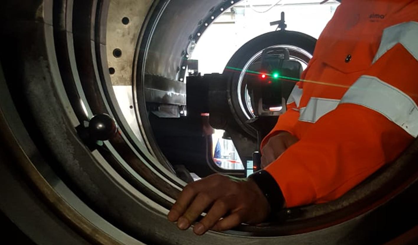
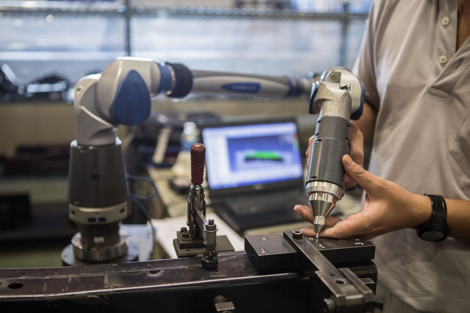
Enhanced Inspection Techniques
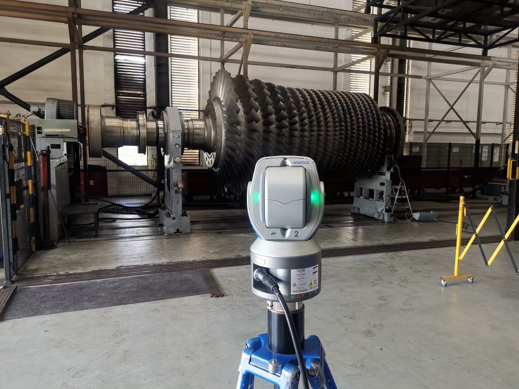
Traditional inspection methods often rely on large conventional instruments such as vernier calipers and micrometers, which require multiple personnel and are prone to human error. To improve accuracy and efficiency, CMM (Coordinate Measuring Machine) arms and laser trackers can be utilized. These advanced tools allow for precise measurement of inner rings, stator blades, turbine jigs, shafts, and large components like the outer ring of the diaphragm with the following benefits:
- Reduced Measurement Time:
CMM arms and laser trackers significantly decrease the time required for measurements. - Consistent Results:
These tools provide consistent and repeatable measurement results, minimizing the risk of human error. - Automated Digital Reporting:
Measurements can be documented and analyzed automatically, generating digital reports that streamline the inspection process. - Improved Installation Precision:
By measuring the turbine’s original position, these tools can monitor and restore components to their original state during installation, enhancing overall precision.
Modern turbine design and operation benefit immensely from advanced machining and inspection techniques. Utilizing in-situ laser-controlled milling and CMM and laser tracking technology ensures that turbines operate at peak efficiency, with precise metal-to-metal seal fits and accurate alignment.
For expert machining and inspection solutions that enhance your turbine’s performance, contact us today. Our team specializes in advanced technologies that deliver consistent, precise results, helping to optimize your turbine systems for longevity and reliability.
Why Choose Us?
- Extensive Equipment Inventory:
We maintain a robust fleet of equipment and accessories, including 5 CSLMs, 2 XL CSLMs, 4 XY milling machines, and 1 low-profile CSLM for air freight. This ensures we can handle multiple projects simultaneously, providing the flexibility your project needs. - Expert Logistics Coordination:
Our experienced logistics coordinators work seamlessly with a network of trusted forwarders to transport our equipment to any location, ensuring timely delivery and smooth project execution. - Highly Skilled Technicians:
Our team of technicians brings extensive experience across various project setups and an in-depth understanding of machine capabilities, allowing us to optimize machining efficiency on every job. - Custom Tooling Solutions:
With a vast stock of customized cutters, we can tackle even the most unique profiles required for your design, ensuring precision every time. - Precision and Quality Assurance:
We use a wide range of calibrated measuring instruments to validate machining results, ensuring complete traceability and adherence to your project’s specifications. - Commitment to Safety:
Safety is always our top priority. We adhere to strict safety protocols to protect both our team and your project. - Innovative Engineering Design:
Equipped with 3D Solidedge CAD software, our engineering team can design and customize machines, simulating setups to minimize downtime and maximize productivity on-site. - Dedicated Project Management:
Each project is overseen by a dedicated project engineer and manager, ensuring that every detail is meticulously handled and deadlines are consistently met. - In-House Workshop in Singapore:
Our fully equipped Singapore workshop allows us to fabricate parts and accessories on demand, significantly reducing turnaround times and keeping your project on track. - Proven Track Record:
We have a history of delivering on our commitments, consistently completing projects within agreed critical paths to keep your project on time. - Uncompromising Quality:
Quality, safety, and timeliness are the cornerstones of our business. We make them our utmost priority in every project we undertake.
By choosing us, you gain a reliable partner who is invested in the success of your project. We deliver precision, efficiency, and commitment—ensuring that your project is completed to the highest standards.